
News
What Is Continuity?
Jul
Continuity is the idea that two things are electrically connected or continuous. In order for electricity to flow through an electrical circuit there can’t be any breaks in the pathway or there won’t be a continuous flow of electricity. Put simply, imagine a road with a drawbridge. When the bridge is up, no traffic can flow across it until it is closed, remove the break in the road. When there are no breaks in the circuit, there is a path allowing continuous movement. This will keep the current flowing and can be thought of as continuity.
Why Is Continuity Important?
Continuity can help you determine several things during the testing and troubleshooting phase:
- Determines if a circuit is open, closed, or shorted.
- Determines if a fuse is good or blown.
- Makes sure a switch is operating properly.
- Verifies wires operating on the same circuit.
- Validates whether wire and cable assemblies are functional.
- Helps test resistance of conductors.
The key is understanding what continuity is and how it works, as it can be extremely beneficial in many circumstances and will be required in almost all electrical situations. Continuity is critical in troubleshooting, service calls, and repairs on cables that are needed for temporary power applications. Watch our video demonstration on how to test for continuity at the bottom of this blog.
How To Test for Continuity?
Supplies Needed:
To begin, you will need a multimeter to test the circuit at hand. Some great options for multimeters include:
- Digital Clamp Meter, True RMS, 600 Amps (Used In Our Video Demonstration)
- Fluke 87-V Digital Multimeter
- Amprobe AM-570 Industrial Digital Multimeter
Secondly you must identify the circuit that you’d like to test, and you’re ready to start!
Steps to Follow:
- To begin, the most important step is turning OFF all electricity at the circuit breaker or switch. Without completing this step, you will be putting yourself at risk of electrocution and damage to your multimeter.
- Next, you can start by plugging in your leads to the corresponding COM jacks on your multimeter. The red lead will go into the positive COM jack and the black lead will go into the negative COM jack.
- Now that your multimeter is ready for use, you will turn on your device and set it to the continuity function which is depicted by the soundwave symbol.
- Check that it is on the correct setting. The multimeter should display “OL” (Open Loop) on the screen. To double check that you’re on the correct setting, touch the metal probes of your leads together and you should hear a loud beep – indicating continuity is present. Now you’re ready to test for continuity.
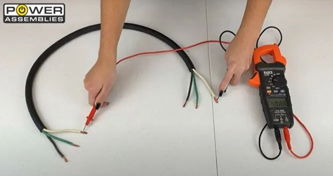
- If you have multiple wires that are not indicated by a color or number, start by holding one of your leads to one end of the wire you would like to test, and touch your other lead to one of the wires on the opposite end.
- You will maintain one lead on the wire you are testing for and use the other hand to go through each individual wire until you find the corresponding end. The multimeter should beep and display a reading for the appropriate amount of resistance in Ohms instead of the open loop symbol (OL).
- Continue this process to verify each wire at hand and mark them accordingly using a number book or phase tape to indicate which wire is which.
These general instructions can be used in many different applications of testing for continuity. Now that you have been able to follow these steps you are ready to put your skills to the test and begin testing for continuity in different ways. For a visual demonstration and more understanding, take a moment view our YouTube video below and don’t forget to like and subscribe to our channel!